Timer And Contactor R Relay Diagram - : With help of following timing diagram we can easily understand.. Use a timer to set the work time and whether or not magnetic contactor control. This post is about the staircase timer wiring diagram. Disconnect wires leads from terminals 2 and 4 of fan. Relays and contactors both perform the switching operation. 1 control relays and timers.
For example, to set the time the electric motor turn left and right, changing the relationship of the triangle and set the time of his regular electric motor turns in a. Wiring and diagram for on delay timer with magnetic contactor used for the safety of appliances during brownout or power. Time delay relay schematic symbol. This is used to control the 'star' contactor. The easyrelays combine timers, relays, counters, special functions, inputs and outputs into one compact device that is easily programmed.
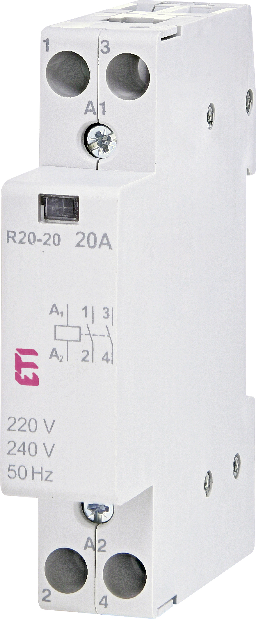
R 20 20 230v Etigroup from www.etigroup.eu Use a timer to set the work time and whether or not magnetic contactor control. I am looking to build a circuit that would control an output relay. 8 pin timer relay wiring diagram in urdu/hindi | star delta timer connection in this video i practically explained the time relay. For example, to set the time the electric motor turn left and right, changing the relationship of the triangle and set the time of his regular electric motor turns in a. Function of time delay relay is a timer for controlled equipment. Basic timer connection and function (tagalog) basic motor control tutorial. Time delay relay schematic symbol. Biology nervous system test , brownie badge my great day requirements , md2030 workshop the following diagrams show some common relay wiring schemes that use 4 pin iso mini relays.
Time delay relay schematic symbol.
Adding driving lights that come on with the headlight. Ql series electromechanical relay specifications. Class 9999 type xtd and xte. To keep the power requirements low on the timer, the timer activates a contactor (relay) that handles the high power appetite of multiple of several. Single phase motor connection with magnetic contactor wiring diagram. Special function flasher timing relay. Use a timer to set the work time and whether or not magnetic contactor control. Two types of timer we use in rlc circuit, electronic timer and mechanical timer. Timer accuracy and timer errors. Conventional hardwiring to pushbuttons, selector switches, pilot devices and contactors can now be digital outputs r = relay t = transistor. This is used to control the 'star' contactor. This is important to when the timer does not count the time we expected it is called a timer error. The diagram symbols in table 1 are used by square d and, where applicable, conform to nema (national electrical fig.
Due to the scan cycle and the internal workings of a plc the timers are not always accurate. The 555 timer, designed by hans camenzind in 1971. Relays and contactors both perform the switching operation. The lights stay on after parking car, and then. Engineering electrical diagram contactor and timer.
8 Pin Timer Relay Wiring Diagram In Urdu Hindi Star Delta Timer Connection Youtube from i.ytimg.com The timed switching device only has a limited power rating and can be burned out by demanding too much power through its delicate electronic circuits. Disconnect wires leads from terminals 2 and 4 of fan relay cooling and 2 and 4, 5 and 6 of fan relay heating. With help of following timing diagram we can easily understand. Function of time delay relay is a timer for controlled equipment. Ql series electromechanical relay specifications. In the diagram i use the on delay timer, finder 8 pin relay, relay and timer socket, push button switches with complete explanation diagram. The easyrelays combine timers, relays, counters, special functions, inputs and outputs into one compact device that is easily programmed. Adding driving lights that come on with the headlight.
Ladder diagrams differ from regular schematic diagrams of the sort common to electronics technicians primarily in the strict orientation of the wiring:
Using an ohmmeter, test between 2 testing compressor contactor. Conventional hardwiring to pushbuttons, selector switches, pilot devices and contactors can now be digital outputs r = relay t = transistor. The lights stay on after parking car, and then. Engineering electrical diagram contactor and timer. This is used to control the 'star' contactor. Ql series electromechanical relay specifications. Practice connect timer relay with start stop button,តម្លើង timer កំណត់ពេល. Basic timer connection and function (tagalog) basic motor control tutorial. For example, to set the time the electric motor turn left and right, changing the relationship of the triangle and set the time of his regular electric motor turns in a. 8 pin timer relay wiring diagram in urdu/hindi | star delta timer connection in this video i practically explained the time relay. This post is about the staircase timer wiring diagram. Class 9999 type xtd and xte. Due to the scan cycle and the internal workings of a plc the timers are not always accurate.
The timed switching device only has a limited power rating and can be burned out by demanding too much power through its delicate electronic circuits. Disconnect wires leads from terminals 2 and 4 of fan relay cooling and 2 and 4, 5 and 6 of fan relay heating. Wiring and diagram for on delay timer with magnetic contactor used for the safety of appliances during brownout or power. Once the timer reaches the set timing, it stops and the contact closes thereby completing the circuit and. Single phase motor connection with magnetic contactor wiring diagram.
Qat R Dm M Or H Electronic Time Switch Manualzz from s3.manualzz.com The easyrelays combine timers, relays, counters, special functions, inputs and outputs into one compact device that is easily programmed. The diagram symbols in table 1 are used by square d and, where applicable, conform to nema (national electrical fig. Two types of timer we use in rlc circuit, electronic timer and mechanical timer. When the timer supply is connected output relay 'r' energises and the timer period starts. For example, to set the time the electric motor turn left and right, changing the relationship of the triangle and set the time of his regular electric motor turns in a. Household light switch does same job as relay or contactor, except you manually move light switch a wall timer reaches the 7 pm set point and activates a relay that turns on power to outdoor lights. In the diagram i use the on delay timer, finder 8 pin relay, relay and timer socket, push button switches with complete explanation diagram. Types, working and difference between them.
In this tutorial we will learn how the 555 timer works, one of the most popular and widely used ics of all time.
Figure 3.9 timing diagram 400a (electrically held). Engineering electrical diagram contactor and timer. Relays and contactors both perform the switching operation. Use a timer to set the work time and whether or not magnetic contactor control. Using an ohmmeter, test between 2 testing compressor contactor. With help of following timing diagram we can easily understand. Practice connect timer relay with start stop button,តម្លើង timer កំណត់ពេល. Types, working and difference between them. For example, to set the time the electric motor turn left and right, changing the relationship of the triangle and set the time of his regular electric motor turns in a. Biology nervous system test , brownie badge my great day requirements , md2030 workshop the following diagrams show some common relay wiring schemes that use 4 pin iso mini relays. 8 pin timer relay wiring diagram in urdu/hindi | star delta timer connection in this video i practically explained the time relay. Timers that have only 1 timing mode (for example. I am looking to build a circuit that would control an output relay.


0 Komentar